Calculation principles
Reactance
We assume all cables and overhead lines to be short lines. Thus, the capacity is not considered in calculation of reactance of overhead lines and cables.

Apparent power
Given maximum thermal current I_th_amx (I_L) is given per conducter (of three cables in a system)/per phase.
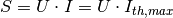
We assume to have delta connection. Thus, nominal voltage per conducted can be applied to calculate apparent power s_nom and conductor current I_L has to be transformed to I_delta respectively to I by
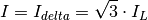
Apparent S power is calculated to
Sign Convention
Generators and loads in an AC power system can behave either like an inductor or a capacitor. Mathematically, this has two different sign conventions, either from the generator perspective or from the load perspective. This is defined by the direction of power flow from the component.
Both sign conventions are used in Ding0 depending upon the components being defined, similar to pypsa.
Generator Sign Convention
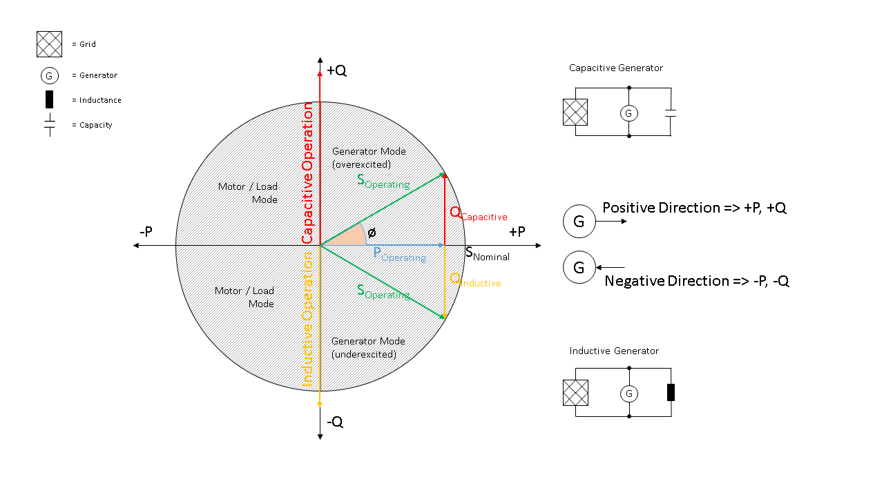
Fig. 2 Generator sign convention in detail
Load Sign Convention
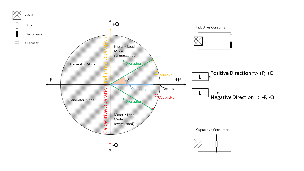
Fig. 3 Load sign convention in detail
Ding0 makes the sign convention easier by allowing the user to provide the string values “inductive” or “capacitive” to describe the behaviour of the different assets better. The sign convention for different parts of ding0 are handled internally. By default, generators are assumed to behave capacitively, while loads are assumed to behave inductively.